Build a Music PC - XP2000 - super-cheap!! [pt2]
Ask a question about this subject?
Post a question direct to our forums and get mailed when a reply is added!
There are 3 viewer comments posted to this page - Read

Author: admin
Date: 06-Nov-02
Build a budget 2000 Athlon XP music PC - Page 2 - Core parts, build to Boot
So we get out the case, and god is it ugly... I knew that, but I just wanted to get a quick all in one payment and that's all they had, of course if i had more time i could have choosen from all sorts of rather tastier looking cases, but so what... Ok, it looks like Darth Vader's codpiece, so mebbe i'll spray it matt black and do a dry-brush 'Mad max/sci-fi' look to it, and that chrome gothic/startrek looking trim with the switches & activity lights on it will then look quite funky perhaps!... Well, you could do that... If I've time I'll do it.
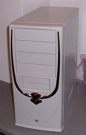
What IS quite handy with the arrival of more USB connecting controller devices in this industry, is the front access USB connectors, but you can certainly get a much nicer looking case for the same �30 quid or whatever I paid... The Duron system I built has a realy tasty case with a sort of see-thru 'imac' style plastic cowling round the cdrom bay etc... Actualy, now I've got the digital camera sorted out (the Kodak one was well crap) I can add a page about the Duron system with a few snaps cos it is a SUPER budget build system with a mic pre-amp, mic & master keyboard all real cheap... Anyways, i digress... So we need to open up the case and sort out the locating pegs for the motherboard to sit on, plus the cables and stuff.
First thing to do is clear all the cables out of the way so that the bottom of the case is exposed, and then, MOST importantly, try some 'dry runs' - Some cases are awkward for offering the motherboard up to the brass stand-off legs - I'll say one thing tho... This case might look crap, but it's a good package, - already pre-pegged for the board & with a big bag full of spare locating screws and extra stand-off pegs & washers etc... Ok... Let's define what we have to do to get the machine to booting stage...
- Add any additional brass stand-off pegs, or if the case doesn't have those pegs pre-fitted then you have to fit them all.
- Fit the cpu & heatsink/fan-cooler assembly to the board.
- Fit the memory into the memory slot/s
- Lower the board into place and secure with the supplied screws.
- Link up the power ATX connector
- Link up the power On/off and reset connector leads.
- Add the AGP graphic's card
- Add the floppy drive & keyboard
That's all you need to boot the machine so you can access the BIOS and start your setup - In all probability and most intances these boards now are all set to start. Frankly you can just add everything and boot up and in most cases as long as all is connected properly and all parts are working there's very little if anything to do...
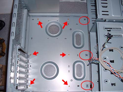
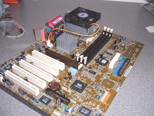
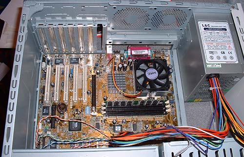
Here was can see the case, open, looking in from the top - Once you've removed both side-panels from the case, always put the thing face UP to work on fitting the board & other components - IF you have a decent bench and a comfortable working height, then by all means use a bench, but I find working on the floor for this bit is good - Put a clean cotton sheet or pillowcase down and put the case on that and get a decent lamp which you can angle into the case to illuminate the proceedings!.... Notice the already fitted brass Stand-off pegs.... If fitted these will line up with the main anchor holes for ATX boards, however, as you can see from the image I have added 3 additional stand-off clip-style pegs down the right side of the board. These additional stand-off clips were included in the bag of spare screws bolts & washers which came with the case...
���������������������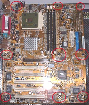
As you can see, the ASUS board has 9 main locating holes... The case is pre-fitted with only 6 stand-off pegs meaning I could fit the board like that & yes it would hold fine with just those 6 fitted pegs, but the right-side of the board won't have much support all down it's edge - and, as that is where the IDE sockets are located and we'll be plugging things IN/OUT of that and applying even mild downward force to that area of the board when we plug in the IDE connectors & ATX power connector then it's best to add some additional support. - Adding extra locating points for the motherboard adds overall greater rigidity to the board fitting, reducing potential vibrations and movement and it also helps to brace the metal case a little, slightly reducing the cases ability to resonate when the power supply & cpu fans are running.. (I do mean slightly) - Anyways, any additional bracing for the board is best fitted... If you take some time fitting the board pegs and getting it right, then you're pc will never give problems when being transported by car (even on London roads!!!)...
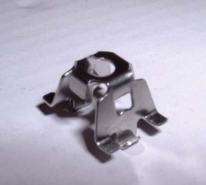 | 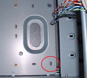 |
That's the small clip-style stand-off peg & that's the holes they clip into on the case back-plate - These 'stand-off leg' clips are simple 'clip-in' affairs, and once clipped into a locating slot they are loose and move around slightly in the locating hole.... Once the board is screwed into this clip it will tighten up a bit, but I like to add some BLUTAC to each fitted clip so it doesn't move at all, or rattle...
Rip off a small bit of Bluetac and soften it up then make a small 'pad' with it, bigger than the locating hole shape.....
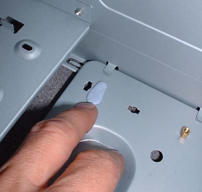
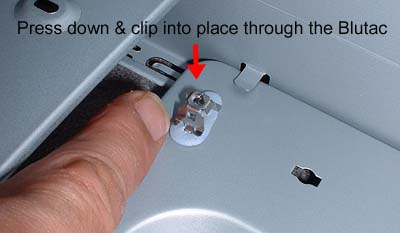
Place the Bluetac 'pad' over the locating hole, then push the clip into place THROUGH this bluetac pad until it snaps into place....
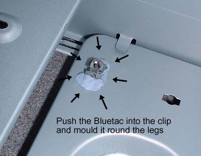
Now mould the overlapping Bluetac into the post until it is firmly seated and movement free and the Bluetac is well stuck to the hole/case-plate & clip.
If no Brass stand-off pegs are pre-fitted to the case back-plate, then fit all the ones you can so they line up with the motherboard holes. A small pair of nose-pliars or some other grips will be needed to tighten the brass stand-off pegs if you have to fit them.... Yes you can finger tighten them, but that last extra quarter-turn with pliars tightens them right up so there's no chance for them to come loose...
Once you're pegs are all fitted, then get the board without yet adding the cpu or ram and try some dry runs lifting the board into the case... Work out the best way to offer the board up to the pegs and at the same time to fit the rear ports (the USB, mouse, keys, audio etc connector blocks) thru the rear of the case. Make sure you do this, you don't want to be farting about working out the best method once the cpu heatsink & cooler are all fitted....
FITTING THE CPU & HEATSINK/FAN ASSEMBLY
The heatsink attaches to the CPU die and dissapates heat away from the CPU core with the assistance of a cooler-fan... It is advisable to have some isopropyl alchohol and cotton buds before you do this... If you DON'T, don't worry... rarely do people go to that trouble when building a pc of cleaning the CPU die & heatsink and then using thermal paste.... All heatsinks come with a fitted strip of 'mating tape' which sits between the CPU die and the base of the heatsink when you fit it... This little strip if thermal tape melts when the cpu is on and forms a bond, bridging the tiny inconsistancies in the roughly machined aluminium heatsink block and helping transfer of heat from the cpu die (the little square bit in the middle of the cpu which get's hot)...
Here's a CPU die on an AMD Duron chip.. it's the small center square bit which is coloured in red in this image to assist identification... On the actual XP2000 Athlon CPU we are using for this build, the CPU Die is actualy a sort of olive green, with text & the AMD logo etc...
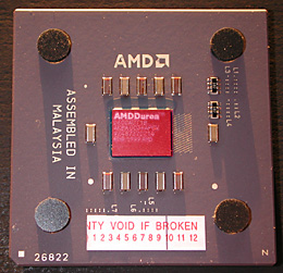
So there is NO need to clean the CPU die first with isopropyl alchohol, BUT if you DON'T have it.. do NOT touch that CPU die with your finger, cos it'll transfer oil from your skin to the CPU die... Keep the CPU in it's baggie until you come to fit it and add the heatsink...
Now, I kid you not... when building a PC, THIS is the hardest bit to do... if you can get thru this nightmare the rest is childs play in comparison... Ironic eh?.. all this super hitech and the biggest problem is still the manual act of fitting the bloody heatsink!!.. it is such a pain in the nuts.. Why they cant use wingnut based clips which screw down gradualy with ease i do not know, but basic heatsinks have the dreaded heatsink 'clip' - a wanky cheap bit of flexible stainless steel which sits over the top of the heatsink and which has to be forced down with great pressure and slipped over the plastic CPU socket clip... This means applying about 40lbs of downward force somehow to a small flange of stainless steel while working right over a delicate motherboard!!!.. one bad slip as you force down and you'll bash the board...
Now, I know in Tiny's or Gateway's sweatshops they'll have a special tool which facilitates this quickly and safely, but for us home-builders who don't have a special tool for this job we have to practice it and work out the best way to do it... I'm only stressing this for newbie who never built a PC... Once you know what to expect it can be done without too much fuss... and despite my dire warnings, I can say I've never lost a board or done damage in scores of builds.... So, it is hard to fit the heatsink & cooler & this you need to REALLY practice before preparing your CPU & heatsink surfaces for the final mating together procedure. To make matters worse, if you DO decide to use thermal paste to gain some slight extra heat transfer ability from the CPU die to the ally heatsink, then once you've added the thermal paste and brought the two surfaces together you DON'T want to move it around. But clipping down the heatsink clip is almost impossible to do without moving the heatsink over the cpu... so practice... Here's how to make it easier...
The base of your aluminium heatsink block will have a peel-off piece of sticker over it with a legend about 'removing it before fitting'.... Leave that ON for now while we sort out which way round the sink needs to sit on the CPU, and which end of the clip you need to attach first.....
Follow the motherboard manual instructions to fit the CPU into the Socket.... This requires lining up one corner of the CPU (which is marked), with the corner of the socket where the socket-lever hinge attaches.... Open the socket lever & raise it fully vertical so the socket is unlocked, and the CPU drops softly into the socket without requiring ANY force... not even mild force!... if it doesn't drop in gently then check it's the right way round and that there are no bent pins underneath - refer to the motherboard manual.....
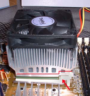
Once the CPU is fitted and the lever is locked back down shut, sit the heatsink on top of the Cpu and check which way round it goes.... You can see in the example above how the heatsink base 'steps' up to match the 'step up' on the CPU socket... Line up the heatsink with this STEP, and lower it onto the CPU...
Now, you'll see the heatsink has a clip/attacher coming out of each side - The stainless-steel clip runs through the center of the aluminium coling fins of the heatsink and protrudes from either side of the heatsink - The protruding part coming out each side has the attaching-clips on them
On ONE side the attatching-clip has NO hinge and is simply angled over at 90 degrees with a thin slot-shaped hole in it which slips over the small oblong hook on the grey plastic CPU socket... The other end of the protruding clip has a hinged moveable clip hanging down off it with the same thin slot-shaped hole in it. The idea being that you FIRST locate & clip-on the NON hinged side, which being the first to be clipped-on doesn't require any hinging... Then to finaly clamp-down the heatsink you use the hinged clip on the other end, which being hinged, allows you to more easily angle it down to the correct position required to meet the small oblong hook on it's side of the grey plastic CPU socket.
So... still working on this as a test dummy trial run, once the heatsink is sitting on top of the CPU, line it's edges up so they are parrallel with the CPU socket, then take the heatsink end-clip WITHOUT a hinge, and slip that over the plastic hook built onto the edge of the grey plastic motherboard CPU socket... This leaves the other end of the clip dangling from the other end of the heatsink... Now you practice bringing down this hinged clip to the point you can hook it over the plastic hook on the CPU socket.... You need to practice this so as to know what to expect when the time comes.... so try that until you are satisfied that you can clip the heatsink on with the minimum of fuss... If you like, you can first put a little piece of clean white printing/writing paper onto the middle of the CPU covering the central CPU 'die' before sitting the heatsink on top of the CPU and experimenting with the heatsink clips... All that does is provide a thin protective bit of clean paper over the central CPU die so as to avoid accidently touching it or scratching it, or getting any dirt on it etc while practicing setting the heatsink onto the cpu... Only first time newbies need to do this really, but having said that, I do this with EVERY BUILD, whenever that is using an heatsink/cpu combi I never used before... I ALWAYS like to try a dry run first, to see how much pressure the hinged clip requires to bend it down & clip it over the cpu-socket connector hook... It's much better to do a dry-run and find out before you commit to the real-run and remove the protective thermal tape covering strip etc.... Basicaly it is like building a bike or car engine, always do dry runs of any connections first before actualy committing to any connection that requires the addition of any bonding paste or mating gaskets etc... that's just a rule of engine building and it carries over well to building PC's!!... Do everything with tender loving care, no excessive force etc...
Now we can move on to actualy fitting the heatsink/cooler assembly... There's two sections for this... WITH thermal paste, and WITHOUT thermal paste... first it is NOT necessary to use thermal paste... As noted already, the heatsink comes with a pre-applied small pad of thermal pate which melts down when the cpu is on to form a bond with the CPU die. When the PC is off, this tape firms up again back to it's cold state (sort of rubbery slightly sticky substance) - These Athl;on CPU's are designed to be built fast with no fuss for OEM's, so it is 100% fine when running a standard PC without any clocking to use the basic procedure for this and just add the heatsink and get on with it....
WITHOUT THERMAL PASTE
Preferably but again, not neccessary, clean the CPU die with isopropyl alchohol - Peel the protecting cover off the heatsink base to reveal the small bit of thermal tape (usualy pinky/orangy colour - Don't touch the tape... Bring the heatsink down onto the CPU as near as you can in one go to it's correct position for the clips to line up with the CPU socket hooks - Lower the heatsink home and attach the first static clip as described in the section above.... Now holding the Heatsink onto the CPU firmly, attach the hinged clip so the heatsink is seated.... and that is that... Now just attach the heatsink cooler fan power-lead to the appropriate motherboard socket (it can only go in the right way round... refer to the m'board manual to locate the power socket for the cpu fan) -
And that is that!!.... you can now add your ram!... then we fit the board top the case...
WITH THERMAL PASTE
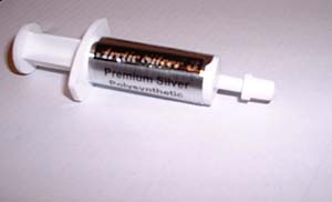
If you bought a cheap generic heatsink like I have for this test build, then the base of the heatsink which attaches to the CPU die wont be milled to a super micron-fine mirror finish... it'll be roughly milled and probably have a slight visible 'grain' to the surface of the aluminium. Then the actual part of the base which connects to the CPU die has this gunky pink square of thermal tape on it which you need to remove... I wont go into this because it needs full instructions which are available on the website of the thermal-paste company - In this case I bought the common brand, 'Arctic Silver 3'
Basicaly, you need to get some isopropyl alchohol and some nail varnish remover (commonest solvent) - Use the nailvarnish remover to clean off the small pink piece of thermal tape from the base of the heatsink - scrape off the thermal tape from the heatsink which will just blob into a rubbery ball as you scrape it off, leaving behind smeary residues on the heatsink surface.... Once it's all removed, clean the area thoroughly removing all vestiges of the thermal tape... Clean it all and wipe off with some lint-free cloth preferably, then clean it off again with isopropyl alcohol concentrating on the center area where the CPU die will meet the surface...
Next, apply a small amount of the thermal paste to the center of base of the heatsink and rub it in and wipe off - This will fill the microscopic inconsistancies in the milling of the base of the cheap heatsink block... Next add a thin layer of the paste to the CPU die and offer the heatsink down onto the CPU and lock it down with the clips....
If you are interested about this procedure with thermal paste in detail, checkout the instructions link....
Arctic Silver 3 - fitting instructions online
Now, I didn't have any solvent to help remove the last traces of the pink thermal tape from the heatsink block.... So what I did instead was, I gently polished off every last visible smear of the thermal tape with 1200 grade wet & dry soaked in isopropyl alchohol until the center of the heatsink block was super-shiny and clean and ready for a final last clean with isopropyl alchohol to remove any last grease or particles of crap... If you do use this method just obviously be careful about wiping off properly and don't get ally dust on anything keep it wet with the Isopropyl alchohol and there'll be no problem...
Here's my prepared heatsink... I've polished it smooth and cleaned it thoroughly with isopropyl alchohol... Then i've worked in the thermal paste and cleaned it off (again you should use a lint-free cloth), leaving this brownish stain where the mciro-fine particles in the thermal paste have absorbed into microscopic surface irregularities of the aluminium block surface...
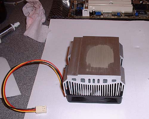
Next using a credit card or razor blade edge & following the 'Arctic Silver 3' instruction at the link above, smooth a very-thin flat film of the paste over the CPU die and you're ready to join them up...
And there she blows!!... Our heatsink and cooler all fitted to the cpu and all ready to go!.... That now achieved the rest is easy... Next we add our ram and we're ready to drop the board into the case...
ADDING THE RAM
Pretty staightforward realy, except to say, IMPORTANT: when pressing in the ram dimm/s make sure the board is located on a solid flat surface, sitting on the foam mat which came with it in the box... do NOT press ram into place with the motherboard on any sort of flexible surface, like the top of the motherboard box for example... we don't want the motherboard to flex when we apply pressure downwards into the dimm slots while pushing down on the dimm/s we are inserting....
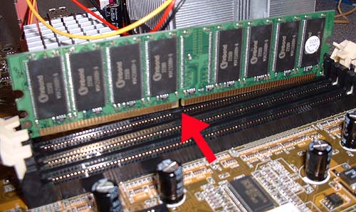
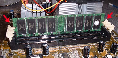
For the newbie, the ram can only go in one way, so no worries there, just make sure the center gap lines up with the seperator on the slot and with both locating clamps at the side snapped fully OPEN, drop in the dimm and ease it into place with firm pressure... when it is fully seated the clamps will clip down into the notches on the side of the dimm locking it fully in place - make sure each clamp on either side is fully closed & locked.... and that is that!!....
Use the first slot, number-1... the dimm slots are marked 1, 2 & 3 on the motherboard next to the sockets, so it's easy to see which to use.... 512mb is the ideal amount for Win98, so I've used that, i do NOT plan to load HUGE sample sets into the pc, but having said that, since the build, this cheap-assed PC has handled some pretty impressive loads with alot of samples for a full-on mix.. More of that in the final section of this article tho... if you plan to use more than 512mb, then you'll need to make some system adjustments in Windows (with win98) - i think 512mb is a perfect amount for a ballsy but cheap PC - so for the newbie, stick to that...
Now our board components are all installed... It's time to fit the engine and start her up for the first burn!.....
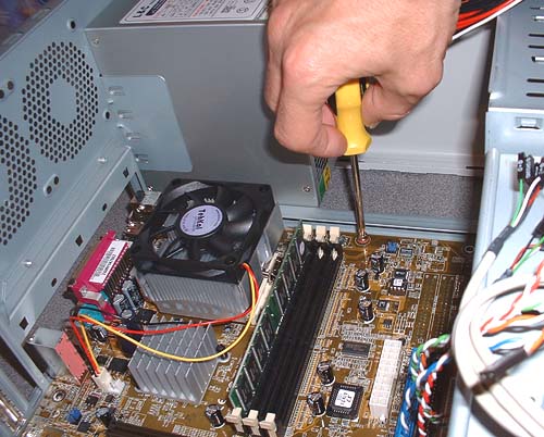
Lower the motherboard into place and using the 9 supplied fibre-washers and the 9 largest little screws, fix down the board firmly all round.... Eee! it's just like rebuilding your 2-stroke twin or triple of a saturday, only easier!...
Note: in the image I've removed the entire rear plate where the rear ports such as USB, Comm & Printer etc reside - You'll see the case has one large hole in it's back, and that is fitted with a shiney pre-formed plate with individual holes for the ports - CHUCK IT! - just pop that whole shiny plate out with some pressure and sling it... Don't worry, just do it, it'll make everything easier and wont make any difference to the PC itself - That plate provides NO worthwhile support for any of the sockets which will protrude through it, so it's worthless keeping it there... Also it just makes dropping the motherboard into place much more difficult.
Anyways, lower the board in and clamp her down with the washers & screws - The screws should go in with easy finger turning... Use the right screws, don't try to force in a PCI slot screw or case screw... The motherboard locating screws are the smaller domed ones with a tiny surrounding flat lip which almost looks like a washer under the screw - There should be only 9 of them as mmentioned already - Also - when you screw down the screws, make it just 'finger firm' - that is hold the screwdriver with your fingertips and apply enuff pressure to just lock it down well.. DON'T screw it tight as anything using your whole palm and hand pressure. We're not locking down a head gasket on a car here!!... easy... firm, that's all... DON'T overtighten...
A word on screws - and I don't mean in The Scrubbs!
Rule 1 - seperate them out before you start the build, into their own types - put each type in a small tea-cup or something so they are all easy to see and choose between.
Rule 2 - IF you drop a screw onto a solid surface (not carpet), NEVER look round to 'see' where it went... As soon as it flies off or drops... FREEZE... Keep totaly still, and LISTEN to where it falls... you'll always find it that way... ah!... it's making me think of the fun you can have sneakily placing a spare woodruff key on your mates workbench when he's just finishing an engine build and watching his face as he spots it & thinks it's from HIS engine!!.. (hours of laughs!).. But i digress!...
FINISHING THE BASIC BUILD
So now we have our board in place, firmly screwed down and all our basic case leads connected... That is: ATX Power On/Off switch lead, HDD activity lead, Reset switch lead, & power LED lead... Refer to the motherboard manual for the connections... Be careful to get these connectors right, it can be confusing studying the manual but take care here to get the right connectors in the right pins... Not because you can damage anything if they are connected wrong, but it might not boot or it might cause your Windows OS install to bum-out later on, so spend some time studying the diagrams in the motherboard manual and get them plugged-in right...
Then finaly, seperate out the main motherboard power loom from the individual drive power leads and connect the ATX power block connector to the ATX connector block on the motherboard - You can't get this wrong newbies... Like fitting the ram, it can only go in one way and there is a clip on one side which plainly goes on the side where the socket clip is, so they meet and lock down... So, board is in all basicaly wired...
Next have a tidy up and then fit your AGP card and keyboard and connect your screen... I'm using a Samsung syncmaster 151S flatscreen which I can tell you is a bargain as they are to be had for around 325 quid cheapest and offer as much screen estate as 17" CRT screen visibility and even some 17" TFT's i've seen... very good screns imo....
Ok so in this build I picked up a Jetway branded Gforce 64mb cheap-ass card for 25 quid...
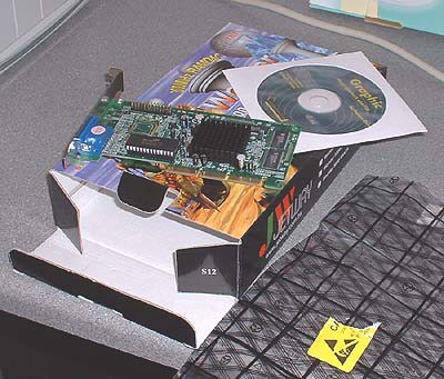
Obviously you can use your old graphic's card if this machine was a rebuild upgrade, or i could have gone round more shops buying individualy and getting specified components in which place i'd probably have gone for a cheap ATI or something... anyways.. as noted already, this is not a 'Classic/pro studio pc' build, where everyone recommends a dual head matrox or whatever - Honestly?... this machine wil deliver gobs of power for a piddling outlay so just think cheap & disp[osable is my motto. You can never build an 'Ultimate PC', and if it's performance you want, trust me this PC at a measly $400 quid will do all you need tracks & plugins-wise to make even complexed deep music....
As for the graphic card not working, clashing badly somehow with the audio side of the PC once we build it?... I can always change it if it's problematic anyway with the dealer... but it was simply bought to test a typical PC-Fair component bundle deal build...
Ok, so add in the AGP card.. This ASUS board has nice AGP slot locking clamp which slides over to keep the old board firmly in place during monitor lead fiddling & plugging in/out....
No need to connect CD-rom or hard-drive etc yet - we dont want to before we've even checked our boot will work... Ok!!... we're ready to boot the machine up & get it ready for the drives, formatting & installing the OS...
Next Article Section - FIRST BOOT-UP INTO THE BIOS + ADD DRIVES
- Article Section 1 - INTRODUCTION, PARTS, THOUGHTS, ETC
- Article Section 2 - THE PHYSICAL PC BUILD PRIOR TO FIRST TEST BOOT-UP
- Article Section 3 - FIRST BOOT-UP INTO THE BIOS + ADD DRIVES
- Article Section 4 - BOOT TO BIOS, DETECT DRIVES - Final tweaks prior to O/S install
- Article Section 5 - WIN XP O/S INSTALL - 'Plug & Play' & 'Standard PC' installs
- Article Section 6 - WIN XP O/S Tweaks - Final BIOS ram & cpu/mem/ratio tweaks
COMMENTS FOR:
'Build a Music PC - XP2000 - super-cheap!! [pt2]'There are a total: 3 comments posted to this page.
Name: robert
Email:
Activity: Hobby-ist
Date: 04-Sep-03
i have just finished building a pc its a socket a athlon t-bird.duron atx motherboard, the thing i am having a problem with is the connectors that go down in the corner for the hd etc,i cant seem toget the right combination i.e the hard drive boots up but i cant get a picture, and because of the case i have this is the only power source for switching on and off any help greatly appreciated
| Article rating out of 5: |
Article 'ratings' were added September 2008, so most articles have no viewer rating
Name: Why?
Email:
Website?: why?
Activity: Professional
Date: 27-Oct-03
You want to know to much, why?
| Article rating out of 5: |
Article 'ratings' were added September 2008, so most articles have no viewer rating
Last added comment
Name: John
Email:
Activity: Hobby-ist
Date: 24-Jan-08
can you adise me where I can get the type of standoff your talking about source please I know they came with your case but I need 4 others any help will be very much apreciated John
| Article rating out of 5: |
Article 'ratings' were added September 2008, so most articles have no viewer rating
'Build a Music PC - XP2000 - super-cheap!! [pt2]'
Note: To cut down on spammers, cookies must be enabled to post comments to this page.
[back to top]