

All about Patchbay's, and how to make your own cheap !!.....
There comes a time in every man & womans life when you have to get a patchbay !!...... Patchbays allow you to route equiptment items to & from the mixer, & each other, without having to grovel around behind your kit.... Everything comes to the patchbay...... From there, stuff can be routed anywhere by the simple insertion of jack-plugs....... patchbays were originally used to route telephone lines to & from lines at the telephone exchange, or in larger hotels & offices etc.
Here we are going to show you how they work, and show you how to make your own !!!..... These things can be expensive, at around L 70 - L 100 per hit, without the leads...but if you do it yerself, then it will be much much cheaper !
Patchbays can have any combination of "Normalised" & "Un-normalised" sockets.... It's just a matter of how you wire them.
NORMALISED PATCHBAY
Ok.... The normalised patchbay sockets, are used to "INSERT" processing units such as compressors & gates into a signal path.
The signal comes into the mixer channel.....through the "Gain", or pre-amp....then through the EQ section..... Once it has passed there, the signal is routed to an insert socket....(there is usually one on each mixer input channel, at the top, with the mic & line inputs)
From the insert socket, the signal then flows back to the rest of the channel, (the aux sends, busses to subgroups & channel fader to master out etc)
Now.....the signal will flow through the insert socket, UNLESS....something is plugged into the signal path..... So..we insert a stereo jack plug into the Insert socket........That stereo plug, carries the channel signal TO our patchbay via the RING of the stereo plug....along a cable...into the patchbay....through the patchbay socket pair......and back to the mixer channel, via the TIP on the same stereo Insert plug......The send & return signals utilise the + & - wires of the stereo 2 core cable for each direction of signal flow, and share the same earth wire.
 |
- |  |
| (fig.1) | (fig.2) |
Here we have a picture of a standard 1/4 inch mono jack socket (fig.1).... upper & lower views..
(It's helpful here, if you actually have one of these with you as you read this).
You will notice, that these sockets have tabs of metal running over the top, connecting the 2 sets of 2 soldering posts...... When you insert a plug, the inserted plug lifts the 2 metal tabs breaking the connection between these two sets of 2 soldering posts (fig.2).
The 2 lifted tabs, contact with the inserted plug's Tip & Earth.......and the signal flows down the plug wire instead.... Well, this is the key to making the patchbay work.
 |
.. |  |
| (fig.3) | (fig.4) |
As you can see (fig.3).... the "Send" & "Return" signal & earth from the mixer channel insert plug go to a pair of 1/4 inch jack sockets.... The RED & BLUE lines in the diagram, are short little wires that are permanently soldered between the two, to pass the signal through to the second socket...... The clever bit, and the bit that makes these two sockets "Normalised", is the choice of soldering posts that you attach things to.....
As you can see, the signal coming INTO the socket pair, attaches to the posts WITH the lifting tabs...that will still pass the signal THRU, even if a plug IS inserted (fig.3).......The signal then flows (via the two little link wires) thru to the second socket of the pair....WHERE IT IS WIRED TO THE OTHER SET OF SOLDERING POSTS....(the ones that DO NOT attach to the lifting tabs)
If you insert a plug into the lower socket, then the signal flowing THRU, is BROKEN (fig.4)......and the outgoing signal will be replaced by the signal from the inserted plug.
UN-NORMALISED PATCHBAY
"Un-Normalised sockets are simply standard 1/4 inch sockets, where no link is made between the two...... You simply bring the inputs & outputs of your FX & Midikit, and your Aux Sends & Returns from the mixer, all to the patchbay...... Then it is a simple matter to plug Aux Send 1 into a Reverb Input, then plug the Reverb Output into an Aux Return or an Input Channel or whatever.......
For an "Un-Normalised" pair of sockets, simply take a lead with a 1/4 inch jack on one end, and bare wire at the other, then solder the Positive & Earth wires to the Socket Soldering posts......Make sure you solder them to the Posts which are attached to the Lifting Tabs....so that when you insert a jack into the front panel socket on the patchbay, the signal will contact with the plug via the tabs.......
WHAT YOU NEED TO MAKE A PATCHBAY
Well, lets say you want to make a patchbay for a mixer with 8 channels....That's 8 channel inserts in total......So for each channel insert, you need One pair of sockets.
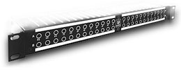
If you also want to bring all your Aux sends and returns, and FX & Processing units IN's & OUT's to the patchbay as well, simply total the number of IN's & OUT's, and count 1 patchbay socket for each...... A patchbay with 40 sockets, (2 rows of 20) will usually be enuff for most home studio's, so:
Right....get the blank panel.....mark out your points for the 40 holes.... WARNING...MAKE SURE THEY ARE FAR ENUFF APART, BOTH VERTICALLY & WIDTHWISE......!!!....yup !!...believe me it's a right fuckin pain in the arse to find they dont fit AFTER you've drilled the holes !!!)
Push the sockets through the holes,and tighten up the plastic nuts......Then, get a foot long piece of the installation cable....and pull out the small signal wires from the outer case......Tin all the socket posts....MAKE SURE YOU ARE TINNING THE CORRECT PAIR FOR UPPER & LOWER IN THE CASE OF THE NORMALISED PAIRS...(see picture above)...
Snip the signal wire you pulled out from the casing into short bits, and connect the posts between the normalised pairs.... THE POSTS THAT CONNECT TO THE LIFTING TABS FOR THE TOP SOCKET OF THE PAIR.....AND THE OTHER POSTS FOR THE BOTTOM SOCKET OF THE PAIR...(see picture above)
Next, take a 1/4 inch STEREO plug.....check which is the SEND & RETURN (tip or ring) on the mixer insert socket, then connect up one end of a piece of installation cable to the Stereo plug.....This goes into the Mixer Channel Insert Socket.
Next....get the other end of that cable....strip it back...(not too much, about 3-4 cm maximum)......then tin the ends, and solder the earth to ONE of the pair of patchbay sockets (we only need to earth one of the pair....remember the pair are linked).
Next attach the signal SEND wire (from the mixer) to the top socket (+) terminal....ATTACH IT TO THE POSTS WITH THE LIFT-TABS.
Next attach the signal RETURN wire (to the mixer) to the bottom socket (+) terminal.....ATTACH IT TO THE POSTS THAT DO NOT HAVE LIFTING TABS
Test out the first one to make sure you got it right.........Run a synth loop through your mixer input channel....plug the stereo insert plug connected to the patchbay, into the channel insert socket.......THE SYNTH SHOULD STILL BE HEARD.
Now......Take a normal 1/4 inch jack lead......and plug it into the top socket of the pair......THE SYNTH SHOULD STILL BE HEARD......
(have a look at the back of the panel.....the jack lead that you just plugged into the upper socket of the pair should be lifting the metal tabs, to which the incoming signal wire should be soldered).....
Now.....Take the other end of that lead you just plugged into the patchbay upper socket, and plug it into another mixer input channel....YOU SHOULD HEAR THE SYNTH NOW ON TWO CHANNELS....
This is known in the trade as: "Taking a sniff"....the way we have wired the patchbay socket pairs, allows us to insert a plug into the TOP or incoming patchbay socket and get a copy of the signal going down the inserted lead....We can send that into a processor unit, such as a compressor, eq, gate etc....but we can also use this feature to split mono signals into 2....then hard-pan them L & R to get some spread....we can even eq them differently to get effects.....We can even use this facility to send a solo instrument signal from a stereo mix over to a tape machine, sampler, or hard-disk system, on a mixer where we have no subgroups to route it out from the mixer.......Cooooool huh ?? (!!)
Ok....so now plug the inserted lead from the patchbay, IN to your compressor or Eq unit input socket.......The compressor lights should start working away.....
Now take another 1/4 inch lead.....plug it from the compressor OUTPUT, back into the lower or RETURN socket of the pair...et voila !!!....er....well it should work if ya wired it as I said !!
Now your synth sound should suddenly change as you plug in to the lower socket....The mixer channel is now routed out from the mixer via it's insert socket.....through to the patchbay....through the compressor, Eq or whatever unit, and back to the mixer channel....Fiddle with the compressor or Eq and the synth sound should change......remember, again we can send the compressed version out somewhere else if we like, by simply taking the return from the compressor, and sending it to say the sampler !!
OK...If that one all works fine, then wire up the other inserts the same...and thats IT !!


i want to build my own 1/4" unbalance patch cables..What cable should i use and who sell it cheap?
thanks
any screened flexible cable - but preferably of a diameter thatll fit inside a 1/4" jack casing... i use 2 core studio-flex with a variety of different colours and lengths to suit different patchbay jobs ... different colours makes it easier to see what is what in amongst the inevitable rats-nest of cables...
Great site, I am pleased to be able to find a site which enables me to talk to other people about one of my great passion.Audio
what's the difference between normalled and half-normalled. you talked about normmalled versus unnormalled, but how does half-normalled compare.
can you tell me how to accomplish the following:
signal out of mixer to patchbay , but create 3,4,or even 5 outs of that same input . I'm wanting to do this so that while one signal is routed thru the board and out of the main outs so I can hear it as it will be recorded i can also send individual channels to my headphone amp for a second mix for headphones. example main mix in left ear and vocal in right. I have aaux insert on my headphone amp and a knob that pans the main signal and aux signal (behringer powerplay pro)
Is it good or bad to have all the grounds on a TT patch bay connected together. I've noticed some people do this and some don't. Which is best?
I need some basic patchbay wiring diagrams. I am trying to "paper" design a project studio and I need to see schematic's from the mic panels all the way to the outboard gear. I still have no visual help to work with. I was hoping to have this with in the week. If there is anyway you might be able to help me in this search, e-mail me with the results. If not... I apprieciate the time you spent to read this through.
I am looking for a decent, fairly inexpensive rack-mountable audio patch bay with 1/4" and RCA inputs and outputs for a home studio. Help!
used patchbays all my life, but wiring my first. Have de-normalized trs bay, do all connections have to be TRS to avoid impedance problems? I have both -10 db and +4 db inputs to deal with....am getting feedback loops from fx processors, etc. Any help?????Thanx.
Nice Site ...that's it
Nice Site ...that's it
Nice Site ...that's it
are there any patchbays that have a usb connection so you can hook up a 24 channel mixer to the computer through the patchbay?
I was running all of my studio gear into my Behringer Eurorack MX2642A, and then out to my cd recorder. However, I have recently picked up the VF-16 Multitrack Recorder/Mixer. I am wondering (as I have never used a patchbay before) if it is possible to get rid of my mixer now and run all of my gear into a patchbay and then out to my multitrack? Is the mixer even needed now since I have the multitrack if I got a patchbay?
Thanks for any help or suggestions!
I'm configuring a patchbay, but I'm unclear on the grounding scheme.
The choices are:
Grounds not bussed
Grounds bussed or
Vertically strapped
It's a 2x26 longframe patchbay with
(4) balanced requiring Phantom power (EO)
(8) balanced (Full-Normalled)
(40) balanced (EO)
(The patchbay is wired balanced although many of the channels will be using unbalanced gear)
what is the correct grounding setup for this patchbay?
Thanks for your help.
My patchbay is a Ultrapatch-Pro-PX2000 from Behringer, I already have my mixer and soundcard connected to it and set at half-normalled and I've gotten a great signal back to my PC! I want to connect my Lexicon rack-mount processor to the patchbay. I've tried just about everything to make it work, I get a strong signal but so far, no reverb (wet). I know it's me, but I've never used a patchbay before. I sure need some help on this! Thank You
what is the proper way to hook up mixer sends and inserts to a balanced TT patchbay?
hello,
are there printable front panel plain views of
24 in/out patchbays that could be used as
studio maps on 8 1/2 x11 sheets of paper?
thank you
im putting in some line in sockets in my studio i have stereo jack sockets but only have 2 wires to solder yet there are about 6 solder points wicth 2 do i use or do i need mono ones hope you can help thanks dave
Can you walk me though the hookups for One ADAT to a Behringer 8 buss mixer, I also have a patchbay to help. I hope to hook up two ADATs as soon as I figure out how to do one. Please help!
Its superb
can I run phantom power on a patchbay?

I want to build a patchbay for a school project, are there any schematics?
Thanks!
Read 23 comments
Add review/comment