Build a Music PC - XP2400 - super-cheap!! [pt1]
Ask a question about this subject?
Post a question direct to our forums and get mailed when a reply is added!
There are 14 viewer comments posted to this page - Read

Author: admin
Date: 01-Mar-04
Build a Music PC - XP2400 - super-cheap!!
Well, we published a cheap Athlon 2ghz KT333 chipset based machine-build last time... Here's a new bargain build for you... a nice cheap, powerful, and upgradable XP2400 machine!...
Here's what �300 quid get's you at the date of this article... A decent board capable of utilising Athlon chips up to 3ghz models and beyond.... 1/2 gigabyte of PC3200 ram, a reasonably fast Nvidia 32mb AGP card, an 80gb ata 133 7200 rpm drive, the actual Athlon 2400 CPU chip and bundled cooler... oh!... and a decent sized case with 350w power supply.
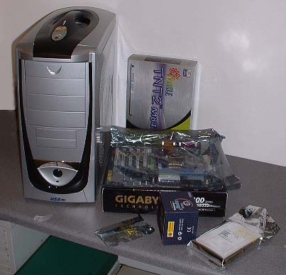
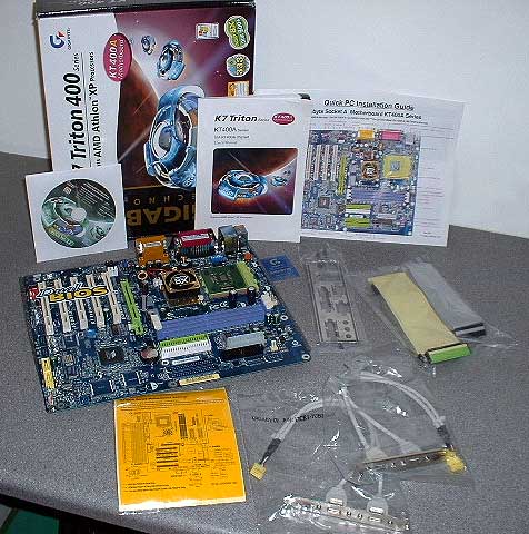
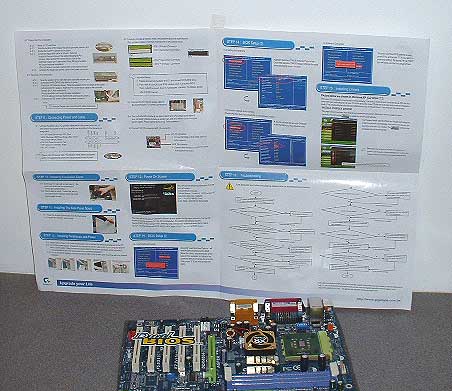
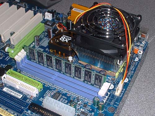
Gigabyte GA-7VAX-A Motherboard
The heart of the system is this Gigabyte ga-7vax-a motherboard - Nice board!... The board includes a drivers cdrom, and some software app's, including a free copy of Norton Internet security, which includes Norton Antivirus, and a clocking & monitoring s/w application. It's a dual-bios board so if for some reason the first Bios get's corrupted or dies, the second one will take-over and the pc will boot...This board is commonly available at PC-fairs and bargain PC parts stores.
This article is for newbies so a quick look at the board main bits is here...
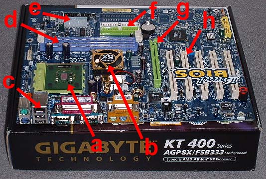
a: is the CPU Athlon chip fitted into the board. - b: is the chipset with it's mini-cooler. - c: is the on-board LAN connector which you can use if you want to connect this computer to another computer or a network of computers. - d: is the memory slots where we plugin our memory. - e: is the power-block connector which connects to the case power-supply. - f: is IDE-1 & IDE-2 bus connectors which we connect hard-drives and cdrom or dvd-drive to. - g: is the AGP graphic's card slot in green. - h: is the PCI slots into one of which we add our soundcard.
The Gigabyte ga-7vax-a motherboard comes with a decent booklet/manual for the board's components and also comes with this 'Quick-start' sheet which folds out from a folded A5 size ..It is double sided instruction guide... The first side shows the board features, and starts with adding the CPU, memory power etc... it's a decent guide done with useful functional graphics.
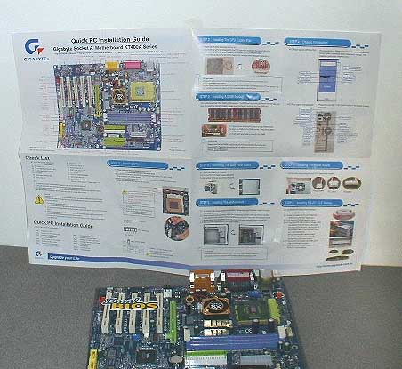
And the other side of the sheet finsihes up with instructions for adding a drive and getting the pc up & running...
GETTING THE BOARD READY TO FIT
It's probably as I mentioned a good idea to read the other Athlon 2ghz build article at Dancetech to get a complimentary build read.... there's much more depth to that articvle for newbies, alot of the thoughts and techniques in that first article are the same for all PC builds, so worth a look I'd say for newbies.... This article will be quicker and more conceise.... Ok, so we start the build as usual by getting the CPU & heatsink/cooler assembly fitted to the motherboard BEFORE we drop the board into the case and fix it down... We don't want to bet trying to fit a heatsink/cooler block inside a case..
So the first thing we need to do is fit the heatsink/cooler assembly....

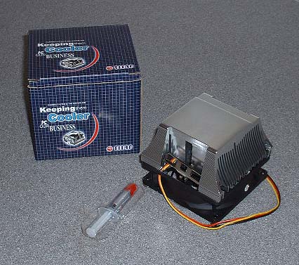
There she is!... Again a common PC-Fair bundled heatsink/cooler - It's 'TITAN' branded, and comes with a small 1.5 gram tube of thermal paste rather than having a strip of thermal-tape fixed across the heatsink block face.
Fitting the Heatsink assembly
First we need to clean the cpu DIE and the Heatsink aluminium block face with some Isopropyl alchohol which I get from the local chemist... This will remove any grease or unseen crap.... You only need to clean the center area about 1 or 2 cm square slap-bang in the middle of the block face....
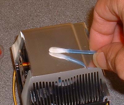
Also you need to give the CPU 'DIE' a swap down with the isopropyl to make sure there's no unseen grease or any stuff like that on the Die.... You never know , mebbe a finger touched it ....that's all it takes to get an unseen greasey deposit.
Dirty huh!.... you can see the difference with an un-blemished cotton-bud in the foreground as comparison... 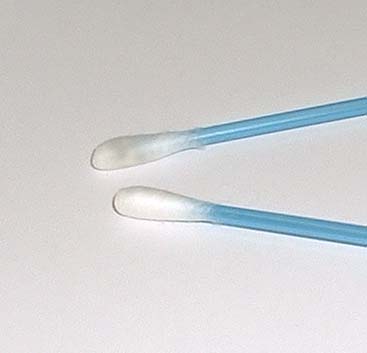
Ok... Next when the Alchohol has evaporated which is a matter of seconds, you add a small blob of paste from the tube - But before you do that, squeeze out some of the paste and dispose of it.... You dont want to use the paste which was sitting in the tip of the tube for ages in a warehouse.... Squeeze out a small blob of the paste...
Get a plain plastic bag and rip a bit off and put it over your finger... Then smear the blob of paste into the block face , and work it round and round in circular movements until ti is worked into the aluminium block..... wipe off until there is just a 'stain' of the paste on the block face... This is just to work the microscopic paste particles into the block face microscopic gaps and imperfections so as to get a better heat transfer from the CPU to the block of aluminium..
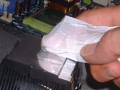
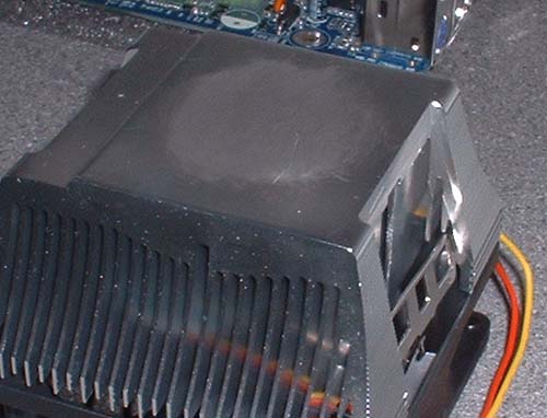
As you can see... here's the block with the paste rubbed in to the center and all wiped off ready to go.
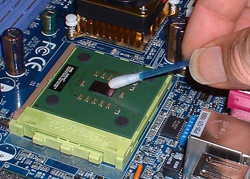
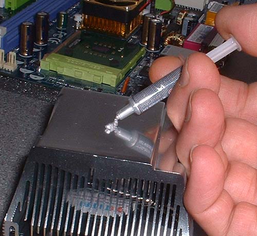
Ok!.... Next, add a small blob to the cpu DIE....
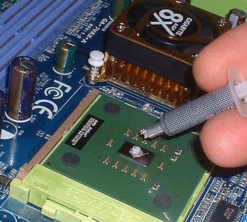
Then using a something with a completely straight but slightly flexible edge, such as a razor-blade or piece of plastic-card etc, you wipe the paste across the DIE leaving a really thin layer of paste on the die.... In this instance, I used a bit of the preformed thin plastic cover which the paste-tube was contained in...
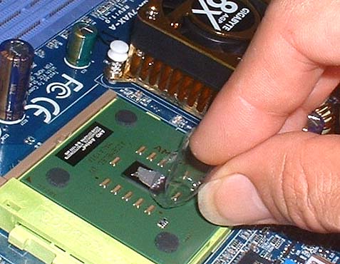
This thin 'spread' of paste is very thin.... enough to cover the surface is all you need, like 1/2 a millimeter.... Don't add a big blob of paste to the cpu DIE or wen you smear it over the surface, it'll ooze out onto the sides of the die... If any paste does go 'over the edge' of the die, scrape it away gently... You just want the fine layer of paste on the cpu die surface only... even and very thin..
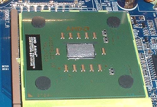
There's the paste on the cpu DIE ready to go...
Next we are going to offer the heatsink assembly down onto the cpu DIE as near as dammit right in place, but we have to get the first set of locating hooks clamped over the retaining hooks on the cpu socket...
The heatsink lines up with the raised 'step' on the edge on the motherboard cpu socket where the edge of the cpu ends....
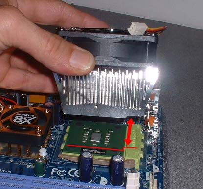
ok.... so we have the heatsink the right way round... Line it up with the cpu/socket and lower the edge down to hook the steel clamp end over the cpu-socket hooks...
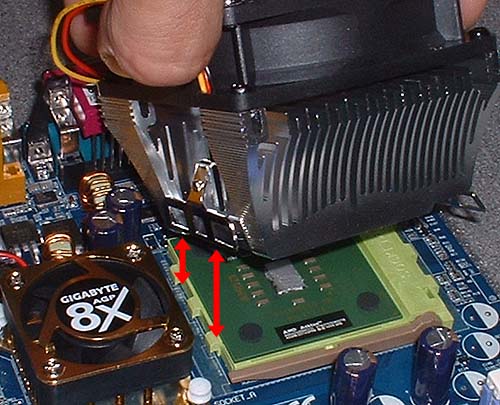
This is actualy really tricky, so it's probably a good idea to do a few dry runs, before cleaning with the alcohol and adding the paste for the final run...
Here you can see the first clamp fitted over the hooks on the green cpu-socket... the clamp is home and dry....
Now we just need to fix the hinged clamp on the other side of the heatsink.... Push down and slip the steel clamp over the cpu-socket hooks...
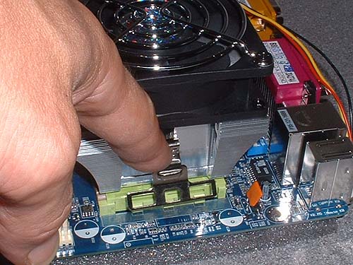
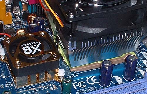
And there she is, ready to go!....
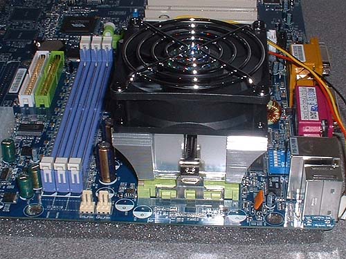
All you gotta do now is connect the cpu-heatsink fan power lead... It's clearly marked on the board and in the instruction sheets & manual and can only connect one way round...
Fitting the ram next...
Referring to the 'Quick-start' sheet & manual for the motherboard, locate memory slot 1, and open the clips fully.... Lower the ram into the slot gently... It can only go in one way round if you line-up the gap in the sockets & the memory board.
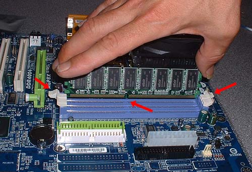
And there's our board ready to go into the case.... it's way way easier to fit the ram & heatsink before adding the board, you'd be mad not to do it that way round in fact...
Fitting the motherboard into the case
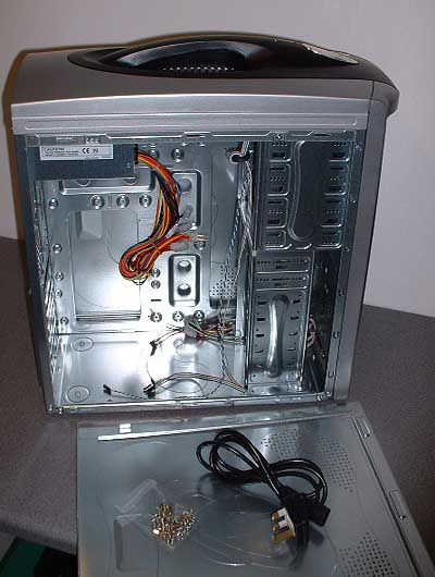
Ok... here's our case... You see these all over the world.. made in china. It was cheap at �31 quid, has a 350w power supply, plenty of space inside .... and it actualy doesnt look too bad! - the carrying handle is actualy very useful indeed!
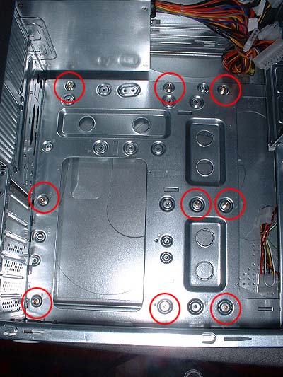
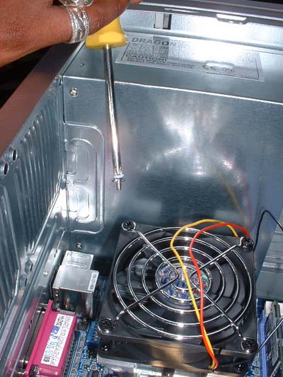
First we need to fit all the required brass locating pegs into the case. The motherboard will be bolted & secured to these pegs...
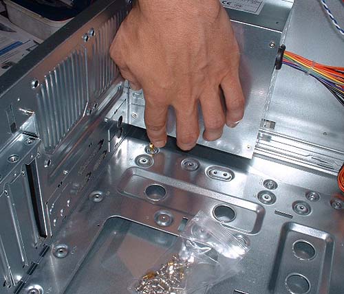
There's all 9 of them located in place to match the board locating holes....You want to tighten these down well... finger tight as far as they will go, then use a small adjustable spanner or pliars (gently) to give them that extra 1/4 turn to really lock them down.... We dont want these coming loose in the future.
Next, knock out the thin metal plates for the motherboard connectors.... Here i'm removing the plate for the LAN & USB connectors...
There's the rear steel plate, with the holes all ready for the board connectors.... You can see a couple of the brass locating pegs in the foreground.
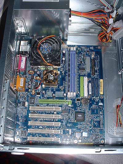
Lower the board into the case onto the brass pegs, and slide the board connection sockets out through the metal plate pre-formed holes...
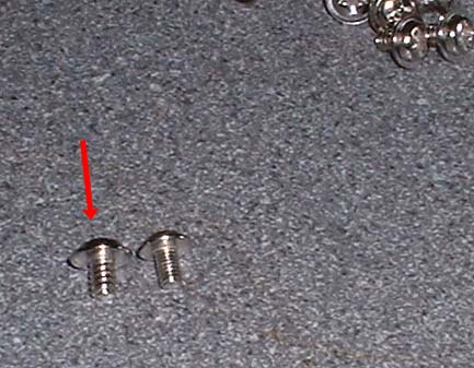
There are two types of smaller screws included in the bag of screws which came with the case... Use the ones with thicker tread on the left....
If you have trouble lowering in a screw to the motherboard, use a tiny blob of Bluetac over the end of the screwdriver so the screw sticks to the driver tip and it can be lowered down into place....
Screw down all the locating screws and the board is now fitted and in place.....
CONNECTING THE MOTHERBOARD CABLES
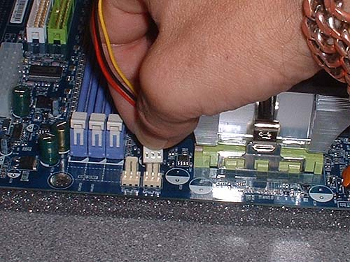
Ok... Now we need to connect up the motherboard connectors for power and the various switches and indicator lights which display on the outside of the case!....
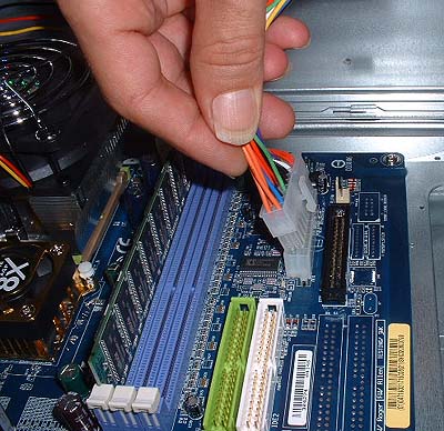
First connect the Motherboard power connector block... it can only go in one way...
Next we need to connect all the little motherboard connectors...
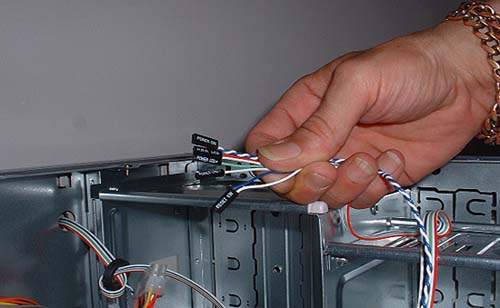
These small connectors are all clearly marked with text lettering on each connector to identify them & are for:
- POWER ON/OFF SWITCH
- IDE ACTIVITY LIGHT
- RE-SET SWITCH
- SYSTEM SPEAKER
- SYSTEM LIGHT
Following the excellent Gigabyte 'quick-start' sheet or manual, both included with the m'board, it's pretty easy to locate and plug in these small connectors.... They all connect in the same corner of the board as shown in the manuals....
You wont damage the PC if you get these wrong, it just might not boot...
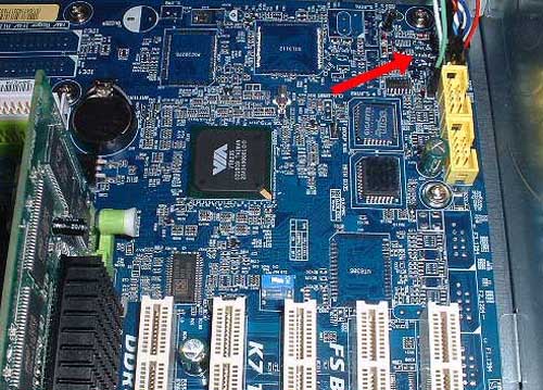
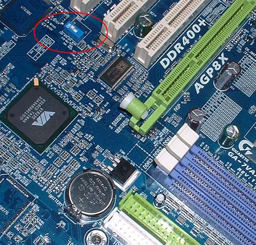
There is ONE MORE important thing to do prior to booting the machine... There is a switch on the motherboard which needs to be switched to Position = ON
FIRST BOOT UP TO CHECK ALL IS WELL!
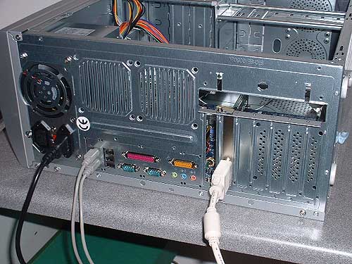
Ok... Now we want to power up and make sure the PC boots!... You do NOT need any drives fitted to do this... All we need is our motherboard power-block connector fitted, and the selection of small connectors for the power on/off switch, IDE-activity light, re-boot button etc... Then we need to connect a Keyboard (and we can connect the mouse too but it's not required to boot the PC.... Oh... er, and connect the screen of course to the AGP card connector... Here's the Mouse, Keyboard & Screen attached and ready to go!....
Ok!!.... Boot the machine and this is what you see....
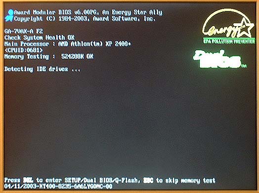
The computer is set to AUTO-MODE and detects and identifies the AMD ATHLON XP 2400 CPU... Then goes on and passes the ram 'Memory Test', then tries to detect an IDE drive...
Detecting IDE Drives...
... and fails of course cos we didn't fit any drives yet!... After a few seconds it'll flip to show this screen, showing a final legend saying:
'DISK BOOT FAILURE, INSERT SYSTEM DISK AND PRESS ENTER'
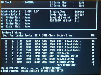
You might find, as in the image above, that on first boot, the screen-image is off-center... In this case it's skewed-off to the left partly obscuring the full screen image... In that case if your screen has an: 'Auto-Setting' button, press it and the screen will reset the screen-image to center and all will be visible, otherwise manualy adjust your screen L/R setting so the image is centered...
Ok... So our PC has booted ok... IF it fails to boot, make sure your mains power is connected and if the case has it's own mains power-switch next to the rear mains plug-socket, make sure that is switched On... If it still fails to boot make sure the little cluster of connecting case leads are connected right... In the rarest of cases a boot might fail cos the memory (ram) fails and is dud, or if the CPU isn't fitted right or the cooler fails or it's fan-power-lead is connected wrong.... But don't worry, I never saw a PC fail to boot in the 50 or so builds I've done... Bad components are rare...
Ok... So it boots! - Eureka!... Now shut the power off by holding down the case front power button until the PC shuts down... Once it's shut down, if the case has it's own mains power-switch next to the rear mains plug-socket, make sure that is switched OFF... Now we can fit our drives...
ADDING THE DRIVES
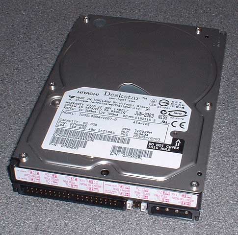
For this build we picked up an 80gb 'Deskstar' drive... It's got plenty of space to get the client going on such a tight budget, and is fast enuff to easily supply the clients required track rates, and it was cheap.. Typical PC-Fair prices for a fast ATA133 7200rpm drive is about �60 quid!.... Other common PC-Fair drives are Maxtor & Seagate... They are all pretty much the same imo... None of these bargain drives have large 8mb cache on-board, but for any songwriting suite requiring 2 track max recording per-take with multiple simultaneous playback of 24, 35, 48 or more tracks, then any of these standard drives are 100% fine as long as you get ATA133 & 7200 RPM speed spec's...
Here's the drive on the bench... It comes like they all do with jumpers already set for the drive to be added to the IDE bus MASTER position...
In the case of this and most low-budget builds FOR MUSIC PC's, the client will use:
A single fixed IDE drive as IDE-0 (PRIMARY) MASTER
A cdrom/cd-writer as IDE-1 (SECONDARY) MASTER
Ok... Here's the procedure to add the drives with this case....
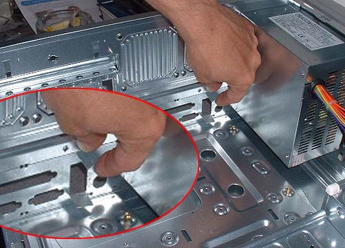
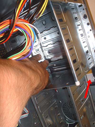
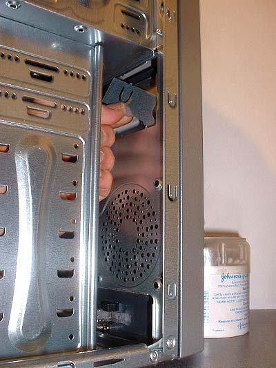 | � | First we must break away some more of the metal case pre-formed plates (like we did earlier to make space for the motherboard rear connectors for mouse/keyboard/USB etc before fitting the motherboard to the case)... We need to remove these metal plates to make room for the FLOPPY and CD-ROM drives to protrude through the front of the case.... It might be better to do this BEFORE adding the motherboard as it CAN be a bit fiddly!... First remove the plate at the top of the lower drive-bay area... This will allow the Floppy-drive to protrude out through the case... By placing the floppy-drive at the top of the lower-drive-bay area, and our hard-drive at the bottom of the lower-drive-bay area, we allow the maximum amount of space around the hard-drive to provide adequate air circulation to the hard-drive which becomes hot while in use... To remove the plates, simply push them forward, then pull them back.... Keep on rocking the plate forward & backward on it's little metal 'hinges' until eventualy it snaps off cleanly.... Be careful not to cut yourself on any sharp metal bits left after the plate has been snapped off!... |
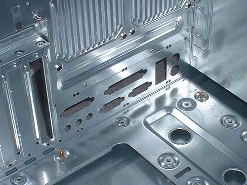
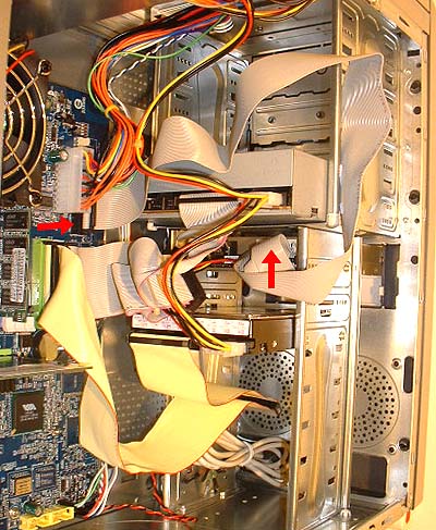
 | � | Here's the Floppy-drive bay inner metal plate finaly worked loose and removed... You can see the cream-coloured plastic floppy-drive bay outer cover-plate behind the removed metal plate.. (indicated by the red arrow)... This also has to be taken off of course to allow the fitted Floppy-drive unit to protrude through the front of the case to allow accesss to the drive & insert disks!... |
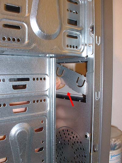
 | � | Now do the same to create a hole for the CD-rom to protrude through!.... As you can see, it means you've got to poke your hand into the upper 5-1/4" (cd-rom width) drive-bay area of the case to take out a plate to make room for the CD-Rom (or CDRW)... It's a bit fiddly.... These metal plates are pre-punched from the metal surrounding them, leaving just a few thin attachment points... You have to move the plate forward and back over and over until the little attachment points snap & the plate drops away.... Note the floppy-drive-bay cover in cream plastic below in the main drive-bay area.... See the little clip on the right clipped round the case holding the cover-plate in place?.... Let's check the next picture... |
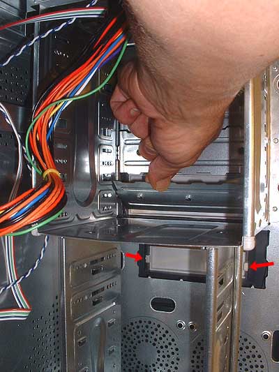 | You can see I'm removing the bottom plate to allow the CD-ROM to fit into the bottom of the upper section 5 1/4" drive-bay area... Also note again the cream coloured plastic Floppy-drive bay cover below the cd-rom drive-bay area, which can be seen more clearly in this image.... Note the two clips indicated by the two red arrows... one each side, holding the Floppy-drive outer case cover-plate in place... To remove this plate, simply snap one of those locating clips inwards a fraction and the cover plate can then be pushed out and off to remove! It's the same for the CD-Rom... Once you've removed the case inner metal plate for the CD-Rom, you also have to remove the outer plastic cover-plate.... This again is done by pushing the left & right clips in a fraction and pushing the cover out & off, just the same as for the floppy-drive cover.... |
DO NOT attempt to remove the plastic outer case cover-plates for the Floppy & CD-Rom BEFORE removing the inner metal plates - You can only remove the outer plastic case cover-plates by accessing the clips on the INSIDE of the case.... If you try to shove a flat screwdriver head into the gap around the cover-plates on the outside of the case and 'prise' them off with a screwdriver, all you'll do is end up scratching & damaging your outer case area... Do it from the inside after removing the metal inner plates... That way you can easily access the locating clips from ther inside and drop the outer cover plates off with ease & cause no damage!
 | Ok.... Now we can fit out two main drives... Slide the CD-Rom into the upper 5-1/4" drive-bay area so the front of the CD-Rom drive protrudes out flush with the outer-case & locate it with a couple of locating screws for now... Then add the hard-drive into the lower drive-bay area & fix that with a couple of screws... We can add the final locating screws at the end of the build, when everything has been tested & the machine is booting OK & we are ready to finaly fix the case together...
|
Ok.... next step is to fit the IDE cables to the HARD-DRIVE & CD-ROM... If you are building any PC wether with TWO seperate physical hard-drives, and a cd-rom or cdrw, or a single hard-drive and a cd-rom or cdrw, then you need TWO IDE CABLES...
Most motherboards only supply a single IDE cable with the board package for adding a max of 2 drives (hard-drive & cd-rom/cdrw) to the Primary (IDE-0) bus, so make sure you have another IDE cable for your Secondary IDE-1 channel... These IDE cables cost a few pounds...

Here's the HARD-DRIVE & CD-ROM cabled to the motherboard....
Here's a better view of the IDE-0 (PRIMARY) & IDE-1 (SECONDARY) bus connectors on the motherboard with the IDE ribbOn-cables attached...

You'll notice that the IDE-0 (PRIMARY) cable is different to the IDE-1 (SECONDARY) ribbon cable.... The IDE-0 (PRIMARY) cable is an 80 strand ATA ribbon-cable required for running faster modern ATA 133 hard-drives... This ribbon IDE cable was included with the motherboard... Normaly for general purpose PC builds you'd just connect the CD-Rom/CDRW & the Hard-drive to the same IDE-0 (PRIMARY) cable, making the Hard-Drive the IDE-0 (PRIMARY) MASTER device, and the CD-Rom/CDRW the IDE-0 (PRIMARY) SLAVE device.... But for our music PC we want to keep the CD-Rom on it's own IDE-1 (SECONDARY) channel and the Hard-Drive on it's own IDE-0 (PRIMARY) channel... In the future when we add a second physical hard-drive for backups we'll add that to the IDE-1 (SECONDARY) channel along with the CD-Rom/CDRW leaving our main programme/recording drive alone on the IDE-0 (PRIMARY) channel
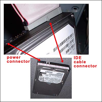
Connecting the hard-drive is easy... You'll see the IDE ribbon-cable has one edge coloured in RED... This red mark indicates strand 1 of the ribbon cable which always plugs-in on the side of the hard-drive IDE-cable socket next to the jumpers & power-connector socket... It's that simple.. Same with the CD-rom/CDRW....
Here's the Power leads you get with the case...
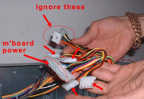
The 4 drive power-connectors are arrowed in Red... The upper circled selection should be ignored... The lower circled selection is the power-block connector we fitted earlier to supply power to the motherboard... You'll also find a smaller Floppy-drive connector in the cluster of cables...
Here we can see the hard-drive, CD-Rom & Floppy-drive all cabled and with their power connectors fitted... The power-connectors only fit in one way, so again it's not possible to make any mistakes there...
Note the Floppy-drive ribbon cable (included in motherboard package) connection points arrowed in red... Again, on the motherboard end the connector can only fit one way if you check the cut-away slot on the connector socket, and at the Floppy-Drive end, the red cable goes next to the power connection just as with the hard-drive and CD-Rom IDE ribbon-cable connectors....
BOOT TO BIOS & BIOS SETUP
Righty-ho!.... Switch any power switch on the rear of the case back ON, and with the screen, mouse & keyboard also attached, we're ready to boot the machine & setup the drives in the BIOS and make a few alterations ready for installing our Windows OS!... heh heh - It's a great feeling when you get her running for the first time!...
Hit the Power button on the front (or top) of the pc-case & the screen comes on... Have your finger ready over the DELETE key on your Keyboard....
When you see this on the screen, or when the ram 'Memory-Test' is being done, hit the DELETE key on the keyboard to step into the BIOS....
To be continued - if you need the BIOS details they'll be added soon - but basicaly to add your drives, see the other XP2000 ATHLON BUILD article in the artcles section for adding your drives - other than that & setting the PLUG & PLAY OS to 'NO', the BIOS is usable as-is - These things all work on automatic settings nowadays unless you want to overclock the PC, which we don't want to do.
If you must have the next section of this article in a hurry - mail us on admin@dancetech.com
COMMENTS FOR:
'Build a Music PC - XP2400 - super-cheap!! [pt1]'There are a total: 14 comments posted to this page.
Name: booj
Email:
Activity:
Date: 17-Jun-04
The article was a great source of information, and I shall be reading it again before building my new system.
The only part I have criticism with is the fact that installing the graphics card is omitted, and it can be seen in the later shots.
thanks
| Article rating out of 5: |
Article 'ratings' were added September 2008, so most articles have no viewer rating
Name: dead__last
Email:
Website?: http://www.doom3.ca
Activity: Hobby-ist
Date: 14-May-05
nice work dood
| Article rating out of 5: |
Article 'ratings' were added September 2008, so most articles have no viewer rating
Name: splintercell_fan : )
Email:
Activity: Hobby-ist
Date: 20-Jan-06
yeah, i'm really having problems with de booting. it says DISK BOOT FAILURE...... but after i'd done the thing you said... i can't get through with de system. i don't know wich command to give it.
| Article rating out of 5: |
Article 'ratings' were added September 2008, so most articles have no viewer rating
Name: Ronald
Email:
Activity: Hobby-ist
Date: 09-Aug-06
how can i fix my computer a hava vaio sony pcvv200g model and is givin my this message "disk boot failure, insert system disk and press enter"
| Article rating out of 5: |
Article 'ratings' were added September 2008, so most articles have no viewer rating
Name: admin
Email:
Activity: Professional
Date: 24-Sep-06
if you have questions, ask them on our forums to get replies
| Article rating out of 5: |
Article 'ratings' were added September 2008, so most articles have no viewer rating
Name: me
Email:
Website?: no
Activity: Professional
Date: 07-Feb-07
Lol old crap, lol, again lol
| Article rating out of 5: |
Article 'ratings' were added September 2008, so most articles have no viewer rating
Name: eduardo jumagdao
Email:
Website?: www.google.com
Activity: part-timer
Date: 10-May-07
its clearly pictures and discuss
| Article rating out of 5: |
Article 'ratings' were added September 2008, so most articles have no viewer rating
Name: Dhawal B. Kuntar
Email:
Activity: Hobby-ist
Date: 25-Jul-07
Very best describtion, I want this type of full description about built multimedia pc and professional pc with Intel Processor and motherboard...
Hopping for reply
thank you
yours faithfully
D.B.Kuntar
| Article rating out of 5: |
Article 'ratings' were added September 2008, so most articles have no viewer rating
Name: NUWAN
Email:
Website?: http://www.angelfire.com/electronic/nuwan/index.html
Activity: Hobby-ist
Date: 02-Jun-08
This web site is good for me to build a computer ram, power, and motherboad.
| Article rating out of 5: |
Article 'ratings' were added September 2008, so most articles have no viewer rating
Name: Jaseman125
Email:
Website?: http://jaseman125.blogspot.com
Activity: Professional
Date: 01-Dec-09
Just buy an Eee PC and connect it to an amp - It's smaller and cheaper.
| Article rating out of 5: |
Article 'ratings' were added September 2008, so most articles have no viewer rating
Name: Rajkumar jaiswar
Email:
Activity: Professional
Date: 05-Aug-11
out look configuration mail in coming and out going
| Article rating out of 5: |
Article 'ratings' were added September 2008, so most articles have no viewer rating
Name: Rajkumar jaiswar
Email:
Activity: Professional
Date: 05-Aug-11
pls solve disk boot faliour system...
| Article rating out of 5: |
Article 'ratings' were added September 2008, so most articles have no viewer rating
Name: dasda
Email:
Activity: Hobby-ist
Date: 18-Feb-12
thank you very much for your tutorial
| Article rating out of 5: |
Article 'ratings' were added September 2008, so most articles have no viewer rating
Last added comment
Name: knifegod41
Email:
Website?: ....
Activity: Professional
Date: 21-Nov-17
BAD VERY BAD
| Article rating out of 5: |
Article 'ratings' were added September 2008, so most articles have no viewer rating
'Build a Music PC - XP2400 - super-cheap!! [pt1]'
Note: To cut down on spammers, cookies must be enabled to post comments to this page.
[back to top]